Voltage controlled Timer

VC Timer
The Timer module is a multifunction circuit designed to create variable pulses from gate signals and function as a Gate Delay
Originally designed as a pulse generator for my LPGs, there are several other functions available.
GATE to TRIGGER, trigger length variable by knob and voltage control
GATE DELAY, delay length variable by knob and voltage control
RAMP and PULSE (with PWM) outputs
DIVIDE BY 2 output
VCO/ GATED VCO, with hard sync and 1v/oct tracking up to about 1.5khz
SR FLIP FLOP, if the length (rate) is set longer than the IN signal length the TRIG out will stay high until a RESET signal is input at the SYNC IN, then the DELAY out will go high.
LEDs can be switched to monitor TRIG & DELAY or RAMP and SAW
RANGE switch sets Fast, Medium or Slow range
SEE THE MUFFS THREAD FOR COMPONENT CHANGES TO EXTEND THE RANGE SETTINGS
At one time someone asked me to design a GATE DELAY for them, the module was never finished (the project was dropped). Later, when I wanted to design a variable trigger generator for my LPGs I decided to use the delay length signal from the gate delay as my trigger. That way I could have a variable trigger and a gate delay in a single module. Then it was obvious to me that patching the DELAY OUT into the RESET input and keeping IN high would cause the module to oscillate so a switch was added for that. Feature creep... Voltage Control, Range switches and 1v/oct tracking were added and this is the module that it became.
Because this was designed as a trigger generator and not an oscillator it will only track up to about 1.5khz, though it can oscillate at higher frequencies. Also only RAMP and SQUARE outputs are available. The GATED VCO resets, this is not a "pause", the ramp wave will always start at zero.
This demo was made using a prototype without a 1v/oct input or fine tune control
Timer Build Notes
Download documentation here: Timer Documentation
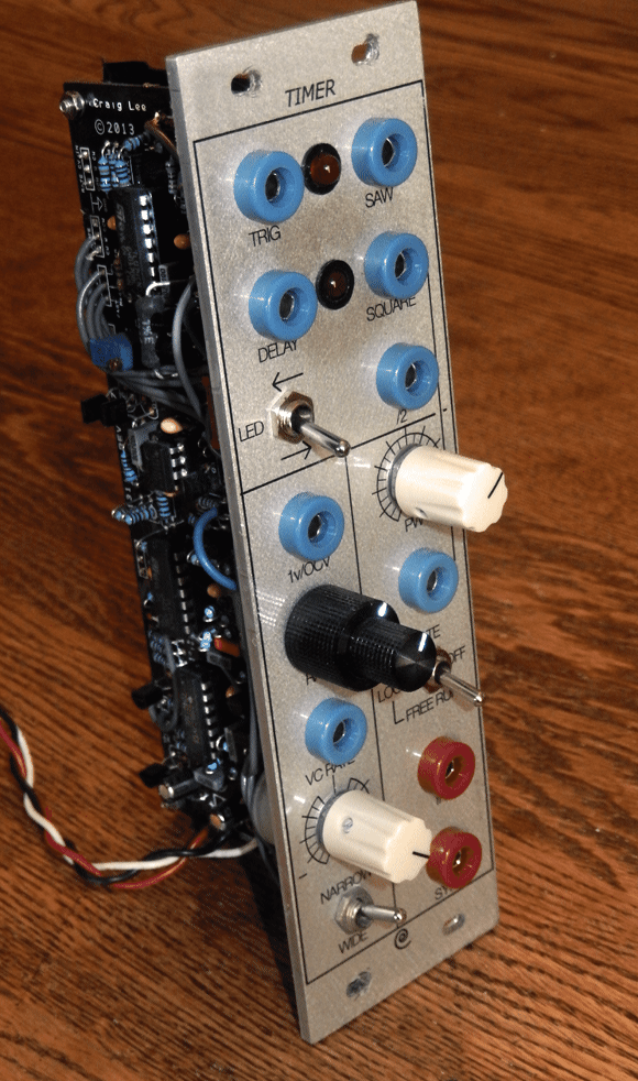
Panels are available from Loudest Warning
*SEE THE MUFFS THREAD FOR COMPONENT CHANGES TO EXTEND THE RANGE SETTINGS* here
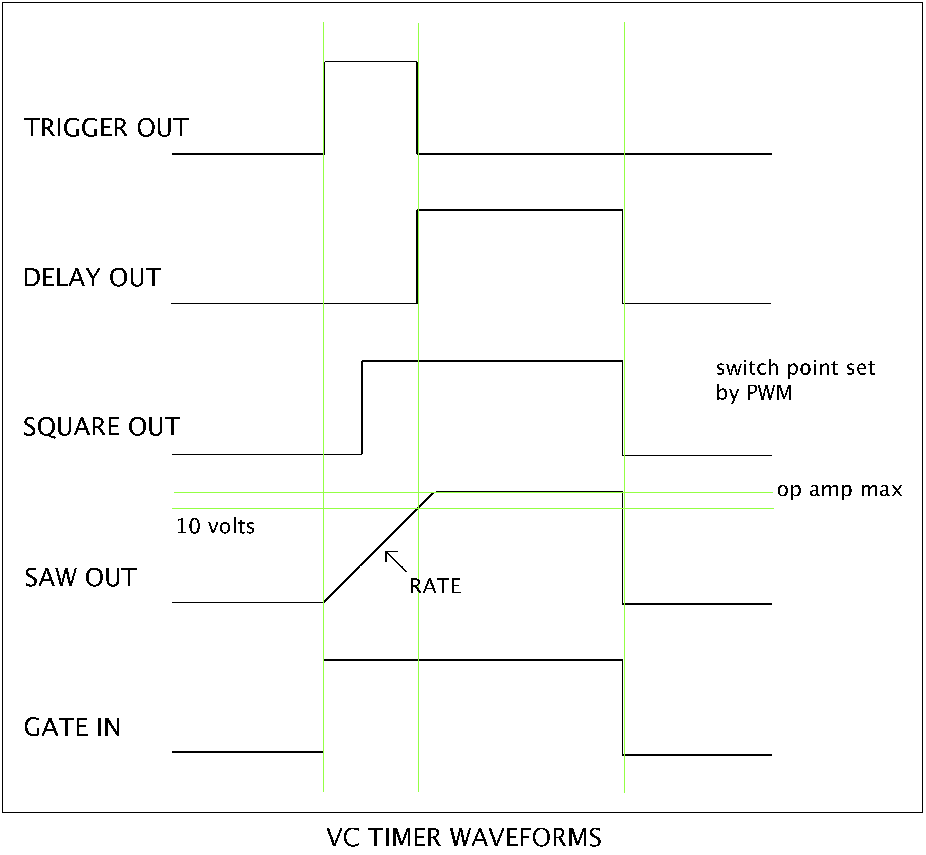
VC Timer Operation
When the input goes high, the TRIGGER OUT will go high and the SAW OUT will rise at the speed set by the RATE pot or CV.
When the SAW OUT reaches 10 volts the TRIGGER out will go low and the DELAY OUT will go high.
The SAW OUT will continue to rise until it reaches the supply rail (or however close to it that the op amp can go.
When the INPUT goes low all the outputs will go low.
The SQUARE OUT is a comparator fed by the ramp signal. A PWM pot and CV set the switching point.
/2 OUT will change states every time TRIGGER out goes hign and will be 1/2 the frequency of the SQUARE OUT.
TRIGGER out can be varied from aprox .5ms to 30 seconds in 3 ranges
SYNC in will return the SAW waveform to 0 volts. If IN is still high the SAW OUT will begin charging again.
LOOP mode will put the Timer in VCO mode. The Timer will track 1v/oct up to aprox. 1.5khz, though it can go higher, just not tracking.
For a smaller build the Timer can be patched to oscillate without the loop switch by patching DELAY OUT into SYNC IN (oscillator sync would not be available then)
The Trigger, Delay, Square and Divide by Two outputs will all be approx. 11 volts with a 12v supply.
If you wish to set the outputs to 5v you can fit 5.6v zener diodes that will limit the output voltage. See the build documents for the locations.
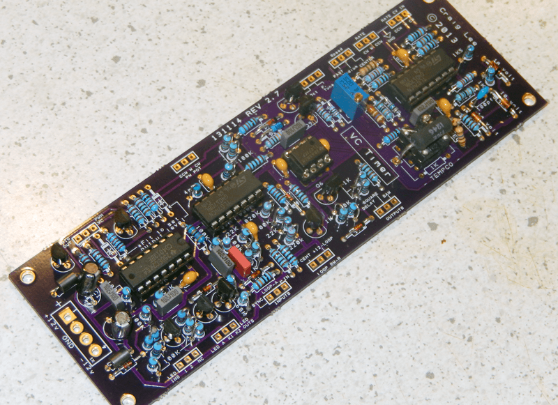
The VC Timer is a 2"X6" PCB and requires an LM394 or equivelent (Matched transistors) and a 1K Tempco resistor.
All other parts are common and easily sourced.
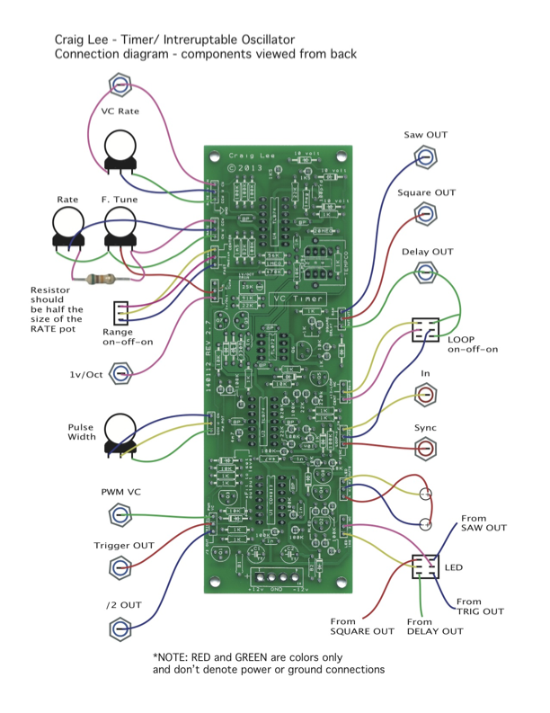
Connection Diagram
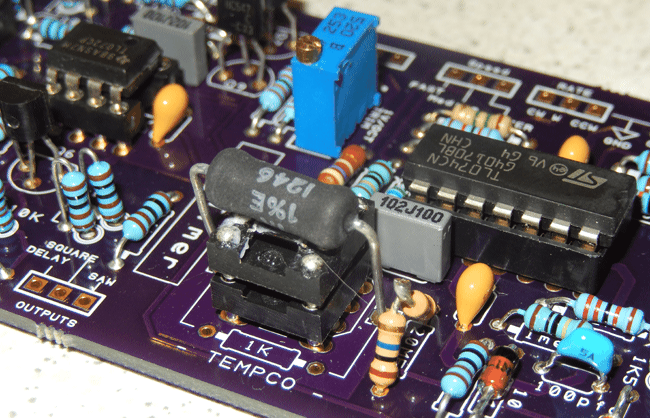
If using a Tempco resistor DO NOT fit 1K resistor in silk location below matched pair
Tempco shown here with an SSM2212 soldered on an IC socket for testing